
VMC Training – Programming, Setup, CNC Milling & Precision Machining
Develop practical skills in Vertical Machining Centre operation, CNC milling programming, G-code, M-code, machine and work coordinates, tool-length offsets, work offsets, Automatic Tool Changer operation, face milling, slots, pockets, profiles, drilling, tapping, machine setup, inspection and troubleshooting.
What Is VMC and Why Is It Used in Manufacturing?
A Vertical Machining Centre is a CNC machine in which the spindle is vertically oriented. It is widely used for milling, drilling, tapping, boring, pocketing, profiling, contour machining and precision component manufacturing.
Programming + Setup + Machining
Effective VMC operation requires more than knowing G-code. The operator or programmer must understand machine axes, coordinate systems, tooling, workholding, tool offsets, work offsets, machining parameters, program verification and component inspection.
NCVT VMC Training connects these topics into one practical manufacturing workflow.
Plan → Program → Setup → Verify → Machine → Inspect
The goal is to understand how engineering drawings, cutting tools, CNC programs, machine settings and measurement work together to produce a finished component.
Understand the Complete Vertical Machining Centre
VMC Milling vs CNC Turning
Both are CNC technologies, but the cutting mechanics and typical component geometries are different.
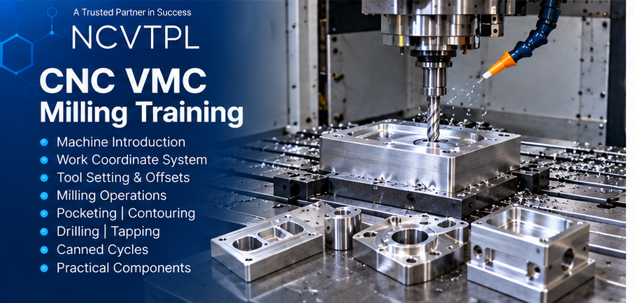
Rotating Cutting Tool
The cutting tool rotates while the job is clamped to the machine table. Typical operations include face milling, slots, pockets, profiles, contours, drilling and tapping.
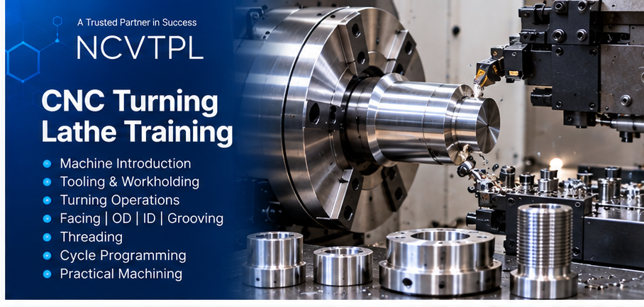
Rotating Workpiece
In CNC turning, the workpiece rotates while the cutting tool machines cylindrical features such as diameters, grooves, tapers and threads.
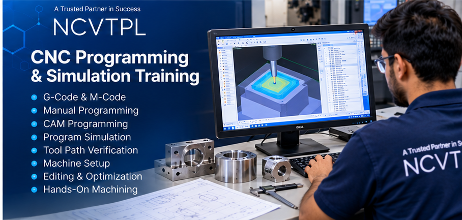
VMC Programming, G-Code, M-Code & Simulation
Learn how a machining drawing is converted into programmed tool movement and verified before cutting material.
Program Structure
Blocks, addresses, sequence numbers and program format.
G00 / G01
Rapid positioning and linear interpolation.
G02 / G03
Clockwise and counter-clockwise circular interpolation.
M-Code
Spindle, coolant, tool change and program functions.
Absolute Programming
Program positions from a defined datum.
Incremental Programming
Program motion relative to the current position.
Canned Cycles
Drilling, tapping and repetitive machining cycles.
Simulation & Dry Run
Verify programs before normal machining.
Machine Coordinates, Work Offsets & Tool Offsets
Work Coordinate Setup
- Machine zero
- Reference position
- Work zero
- Component datum
- X / Y datum setting
- Z datum setting
- Work coordinate systems
- G54-type work-offset concepts
- Job alignment
- Datum verification
Tool Offset Setup
- Tool number
- Tool length
- Tool-length offset
- Tool geometry
- Tool-wear correction
- Tool measurement
- Tool-call verification
- Offset table
- Dimensional correction
- Tool replacement correction
Practical VMC Milling Operations
Milling
- Face milling
- Slot milling
- Pocket milling
- Profile milling
- Contour machining
- Chamfering
- Step machining
- Multi-depth machining
Hole Machining
- Centre drilling
- Drilling
- Peck drilling concepts
- Reaming
- Tapping
- Boring
- Hole patterns
- Canned cycles
18-Module VMC Training Curriculum
A structured progression from machine fundamentals through programming, setup, machining, inspection and troubleshooting.
Introduction to VMC
VMC concepts, manufacturing applications, machining processes and machine capabilities.
VMC Machine Architecture
Machine construction, spindle, table, axes, controller and enclosure.
Drives, Motors & Feedback
Servo motors, servo drives, spindle drive, encoders and axis feedback.
CNC Controller & Operating Modes
Control panel, jog, reference return, MDI, edit, automatic and single-block modes.
X, Y, Z Axes & Coordinates
Axis direction, machine coordinates, reference points, datum and work coordinates.
CNC Programming Fundamentals
Program structure, blocks, sequence numbers, addresses and programming rules.
G-Code Programming
Rapid, linear, circular and machining commands.
M-Code Programming
Spindle, coolant, program control and auxiliary machine functions.
Absolute & Incremental Programming
Coordinate programming methods with practical milling examples.
Tool-Length & Wear Offsets
Tool measurement, geometry, length correction and wear compensation.
Work Offsets & Job Setting
Work zero, datum setting, coordinate offset and job alignment.
Face, Slot & Pocket Milling
Toolpath planning for standard VMC milling operations.
Profile & Contour Machining
Linear and circular interpolation for component profiles.
Drilling, Reaming, Tapping & Boring
Hole machining, positioning and canned-cycle concepts.
Cutting Tools & Holders
End mills, face mills, drills, taps, boring tools and tool holders.
Feeds, Speeds & Cutting Parameters
Cutting speed, spindle RPM, feed, depth of cut, coolant and tool life.
ATC, Verification & Troubleshooting
Automatic Tool Changer, tool calls, simulation, dry run, alarms and machining faults.
Complete VMC Machining Project
Drawing, planning, programming, setup, machining, inspection and correction.
Practical VMC Programming & Machining Exercises
Basic VMC Program
Build program structure and machine movements.
Work Offset
Establish job datum and work coordinate.
Tool-Length Offset
Measure and enter tool length values.
Face Milling
Machine a controlled flat datum surface.
Pocket Milling
Develop and verify pocket machining.
Hole Pattern
Coordinate-based drilling program.
Drill & Tap
Hole preparation and tapping cycle.
Contour Program
Combine linear and circular paths.
Multi-Tool Program
Program sequential tools using ATC.
Complete Component
Drawing to inspected finished component.
Automatic Tool Changer & Tool Management
Tool Magazine
Understand tool storage, pockets and available tool positions.
Tool Number
Relate programmed tool numbers to physical tools.
Tool Change
Understand programmed tool-change sequence and machine operation.
Tool Verification
Confirm correct tool, pocket, offset and clearance.
From Engineering Drawing to Finished VMC Component
A successful VMC job requires planning before machining and measurement after machining.
Read Drawing
Dimensions, tolerance and geometry.
Plan Process
Determine machining sequence.
Workholding
Select vice, clamps or fixture.
Select Tools
Choose suitable cutting tools.
Program
Develop machining sequence.
Set Offsets
Tool and work coordinates.
Verify
Simulation, dry run and clearance.
Machine
Execute controlled machining cycle.
Inspect
Measure finished dimensions.
Correct
Apply wear or offset corrections.
VMC Cutting Tools & Tool Holders
End Mills
Slots, pockets, profiles and general milling.
Face Mills
High-productivity machining of flat surfaces.
Ball Nose Cutters
Contour and curved-surface machining concepts.
Drills
Hole generation and drilling cycles.
Reamers
Hole finishing and dimensional accuracy.
Taps
Internal-thread machining operations.
Boring Tools
Precision internal-diameter machining.
Tool Holders
Collet, side-lock and general holder concepts.
Feeds, Speeds, Depth of Cut & Tool Life
Component Measurement & Dimensional Correction
A CNC program is successful only when the machined component meets its required dimensions and tolerances.
Common VMC Programming, Setup & Machining Problems
Program Alarm
Check syntax, unsupported commands and controller messages.
Wrong Work Offset
Verify datum, coordinate system and work-offset values.
Wrong Tool-Length Offset
Check tool measurement and offset-table entry.
ATC / Tool Mismatch
Confirm tool number, magazine pocket and program command.
Dimensional Error
Check tool wear, offsets, program geometry and component setup.
Poor Surface Finish
Review tooling, speed, feed, rigidity and coolant.
Chatter / Vibration
Check workholding, tool overhang and cutting parameters.
Collision Risk
Use simulation, dry run, single block and safe-clearance verification.
Safe VMC Setup & Operation
Who Should Learn VMC?
Suitable Participants
- ITI Machinist
- ITI Fitter
- ITI Turner
- Mechanical Diploma Students
- Mechanical Engineering Students
- Production Engineering Students
- Manufacturing Engineering Students
- CNC / VMC Operators
- CNC Programmers
- Production Technicians
- Manufacturing Professionals
- Engineering Graduates
Career Direction
- VMC Programmer
- VMC Operator
- VMC Setter
- CNC Programmer
- CNC Milling Operator
- VMC Setup Technician
- Machine Shop Technician
- Production Technician
- CAD/CAM Programmer
- Manufacturing Engineer
- Production Engineer
- CNC Maintenance Technician
Continue Your Manufacturing & Automation Learning
VMC Training FAQs
What is VMC?
VMC stands for Vertical Machining Centre. It is a CNC machining centre with a vertically oriented spindle used for milling, drilling, tapping, boring, pocketing and contour machining.
Does VMC Training include G-code?
Yes. Training covers CNC program structure and G-code used for positioning, interpolation and machining operations.
Is M-code included?
Yes. M-code concepts include spindle, coolant, tool-change and other machine functions.
Are tool offsets covered?
Yes. Tool-length, geometry, wear offset and tool-measurement concepts are included.
Are work offsets covered?
Yes. Learners study machine zero, work zero, datum setting, work coordinates and work-offset concepts.
Does the course cover Automatic Tool Changer operation?
Yes. Tool magazine, tool numbers, tool-change commands, tool verification and ATC concepts are covered.
Which milling operations are covered?
The program covers face milling, slot milling, pocketing, profiling, contour machining, drilling, reaming, tapping and boring concepts.
Is program simulation included?
Yes. Program verification, simulation, dry run and single-block operation are included as part of safe setup.
Does VMC Training include feeds and speeds?
Yes. Cutting speed, spindle RPM, feed, depth of cut, tool selection and machining parameters are covered.
Is component measurement included?
Yes. Training introduces vernier calipers, micrometers, datum verification, tolerance and dimensional corrections.
Is troubleshooting included?
Yes. Topics include program alarms, work-offset errors, tool-offset errors, dimensional problems, ATC issues, chatter, poor surface finish and collision prevention.
Who can join VMC Training?
Mechanical, production and manufacturing students, diploma and ITI students, CNC/VMC operators, programmers, technicians and working professionals can benefit from the program.
Learn VMC From Program to Precision Component
Build practical knowledge in VMC programming, G-code, M-code, tool offsets, work offsets, ATC, CNC milling, machining cycles, job setting, measurement and troubleshooting.
Enquire for VMC Training →